Today I’m gonna show you how to start and create a new project with Keil uVision5 for STM32F4 Discovery.
You just need followings to start:
- STM32F4 Discovery Board
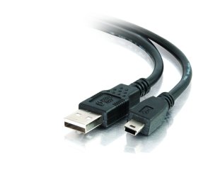
- USB Mini Cable
- Board Kit Driver Software Download
- Keil uVision5 Software (From the link below, go to the Download -> Product Downloads -> MDK-ARM). After you enter your contact information there you can download the program.
https://www.keil.com/
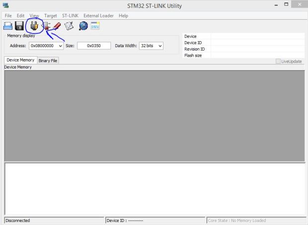
- STM32 ST-Link Utility (Just in case you got problems with your board). From the link below, from Get Software you should give your full name and email information. Then you will get a mail that contains a download link.
http://www2.st.com/content/st_com/en/products/embedded-software/development-tool-software/stsw-link004.html#
Here is our STM32F4 Discovery Board and USB Mini Cable:
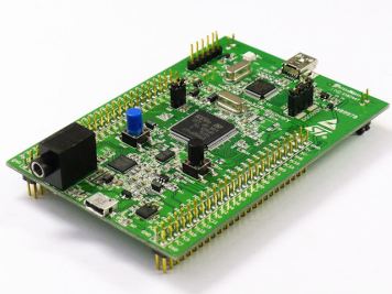
Before you install your driver 1 LED (PWR LED) will turn on red stable and another LED (COM LED) will blink red.
After you install st-link_v2_usbdriver, update your driver.
Device Manager -> Other devices -> STM32 STLink
Right click and Update Driver Software… and choose Search automatically for updated driver software
After updating, driver will be shown in Universal Serial Bus controllers or Universal Serial Bus devices as a STMicroelectronics STLink dongle
Now the COM LED won’t be blink and will be stable red as PWR LED.
For next, install Keil uVision5 which you downloaded before. Now you probably need a device pack. Get the latest version from link below (for now Keil.STM32F4xx_DFP.2.8.0.pack).
Keil -> STMicroelectronics STM32F4 Series Device Support, Drivers and Examples -> Download
http://www.keil.com/dd2/pack/#/eula-container
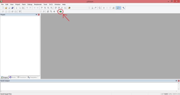
After downloading, open Keil uVision5 and install your pack as shown below:
Click on Pack Installer.
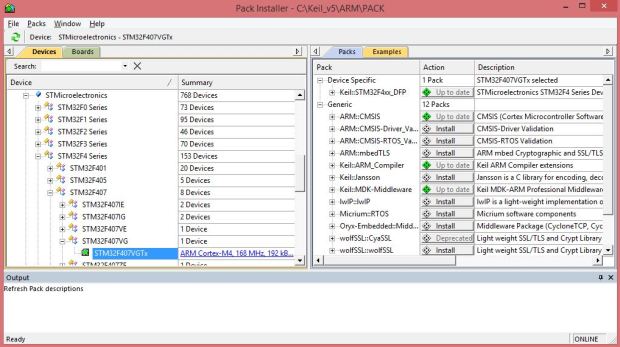
Refresh your Packs (File -> Refresh) (To Refresh you must be online). Then Import the pack you downloaded already (File -> Import…). After you imported the pack you can see your pack as a STM32F407VGTx.
You can start with an example (Blink) project to test your board.
There are some example projects in the pack you downloaded before. From Root address of your Keil uVision5 program choose the GPIO example. But first disable the Read-only protection of the Projects Folder.
Keil_v5 -> ARM -> Pack -> Keil -> STM32F4xx_DFP -> [Pack Version (for example 2.8.0) ] -> Right click on Projects Folder and go to Properties uncheck Read-only and confirm the changes to the subfolders and files.
Now in Keil uVision5 open your example project. Project -> Open Project…
Keil_v5 -> ARM -> Pack -> Keil -> STM32F4xx_DFP -> [Pack Version (for example 2.8.0) ] -> Projects -> STM32F4-Discovery -> Examples -> GPIO -> GPIO_EXTI -> MDK-ARM -> Project (Green Icon File)
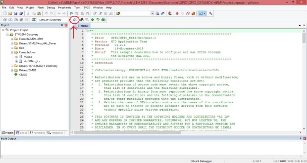
Now set-up the configure for your board. Click on Options for Target…
From Target tab set Xtal (MHz) up to 8.0
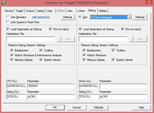
In Debug tab use ST-Link Debugger
In Utilities tab uncheck Use Debug Driver and choose ST-Link Debugger
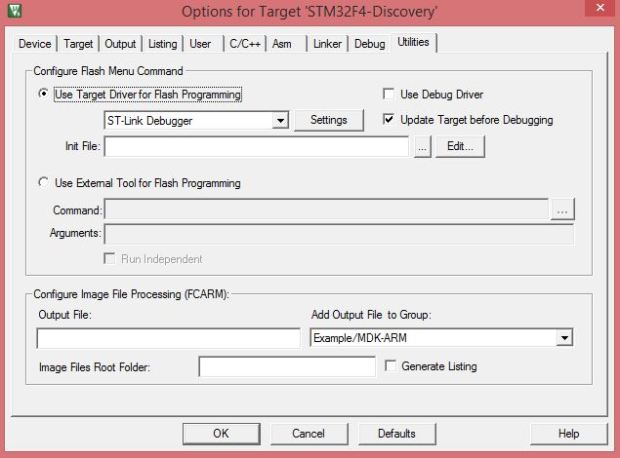
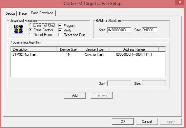
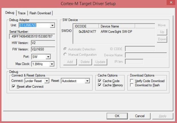
In Configure Flash Menu Command open settings and make sure that in Flash Download tab for Programming Algorithm you’ve added STM32F4xx Flash.
and in Debug tab for Debug Adapter unit ST-Link/V2 is already chosen (whn your board is connected to your PC) and the Port is SW.
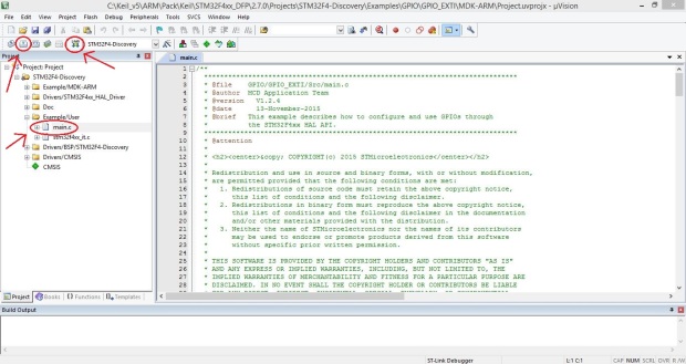
Now open main.c from Example/User Folder in the Project toolbar in the left side.Build you project by pressing F7 or the icon. And Load it to your board by pressing F8 or the icon.
while you are loading your project the LD1 LED on your board will blink red and green repeatedly. It shows that the project is loading to your board.

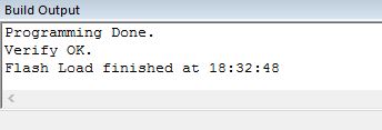
If all the processes gone correctly you will see the these messages in Build Output window in the bottom.
By pressing the Blue Button on your board you can see the 4 LEDs (between the Black Button and Blue Button)turning on and off.
I recommend that to read the User Manual to know better of your board.
Discovery kit with STM32F407VG MCU User Manual Download
For more information and details you can check this PDF. Download
Don’t hesitate to ask your questions if you have some problems.
Masoud

You must be logged in to post a comment.